PRODUCTS
Find products quickly
-
Motor frequency conversion control
-
Motor soft starter series
-
Tbqd series electromagnetic voltage regulating compensation soft starting device
-
Gsdq water resistance soft starter series
-
SDQ series water resistance soft starter
-
GGQ series (high voltage AC motor) high voltage solid state soft starter
-
Dgq series (AC motor) low voltage solid state soft starter
-
Gdcq electromagnetic voltage regulation soft start series
-
GDKQ series high-voltage reactance starting cabinet
-
-
Power system complete equipment
-
Dydzb series low voltage compensation cabinet
-
DDB low voltage dynamic compensation cabinet
-
GWJ series reactive power compensation cabinet
-
GCK low voltage withdrawable switchgear series
-
GGD AC low voltage distribution cabinet series
-
Xl-21 low voltage power distribution box series
-
XGN high voltage switchgear series
-
Kyn28a-12 high voltage switchgear series
-
MNS low voltage draw out switchgear series
-
GZDW DC panel
-
VDK series vacuum circuit breaker
-
-
Compensation product series
Welcome to consult now
Telephone consultation:
Business address:
HPS phase advancer
- Product Description
- Principles and characteristics
- Model definition and selection instructions
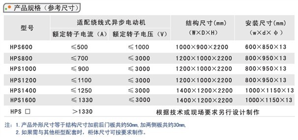
- Technical parameter
- One time plan
The static phase advancer (hereinafter referred to as the phase advancer) is a high-tech product born in the early 1990s in China. However, with the development of society and the progress of science and technology, the technical performance and use of its products have also been well improved and improved.
HPS series phase advancer is mainly an AC-AC converter composed of power electronic devices instead of the traditional self-excited rotating phase advance device, which can achieve better compensation effect and higher reliability.
is suitable for the reactive power on-site compensation of high and low voltage winding AC asynchronous motors. The J type is suitable for relatively stable drag load, and the D type is suitable for working conditions where the drag load is easy to change.
-
The static phase advancer mainly adopts AC-AC frequency converter to add the low frequency voltage of the 50HZ power frequency voltage to the motor rotor circuit at the same frequency as the motor rotor current, and make the additional voltage lag the rotor current by 90° to reach the motor The effect of connecting capacitors in series on the rotor side. This additional voltage is composed of a fundamental wave of 50HZ. Figure 1 shows the relationship between rotor current, additional voltage, and additional equivalent voltage.
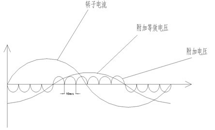
Figure 1 The relationship diagram of rotor current, additional voltage, and additional equivalent voltage
AC-AC inverter working principle diagram
From Figure 1, we can see that the additional voltage follows the rotor current and lags behind the rotor current by 90°. In order to achieve this goal, we must monitor the rotor current to meet our control requirements. Figure 2 is a schematic diagram of AC-AC inverter. CT1, CT2, and CT3 are isolated Hall current sensors to detect the motor rotor current. There are twelve SCRs from SCR1 to SCR12, six reactors from L1 to L6 and the transformer TC to form an AC-AC frequency converter.
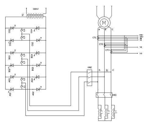
Figure 2 Schematic diagram of AC-AC inverter
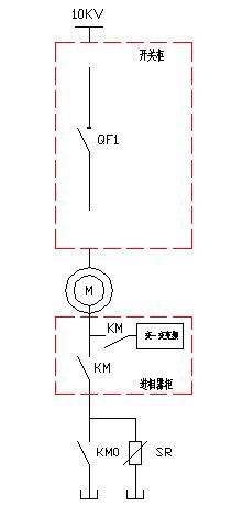
In Figure 2, KM2 and KM3 are interlocking working AC vacuum contactors. Before the phase advance, the rotor circuit of the motor is connected to the starter cabinet by the normally open contact of KM3, but after the phase advance, the normal The open contact converts the rotor circuit of the motor to the phase advancer control circuit.
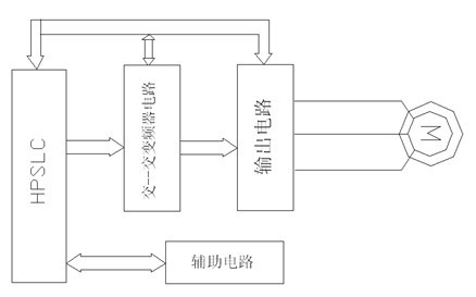
HPSLC special logic controller, it is one of the heart components of the phase advancer. HPSLC is based on single-chip control as the core, composes a loop system and controls various signal units of the phase advancer to realize various functional characteristics of the phase advancer.
Cross-converter
A three-phase frequency conversion circuit composed of thyristors to realize the conversion between the power frequency 50HZ voltage and the low frequency current of the motor rotor, and provide the motor rotor with a same frequency voltage that lags the rotor current by 90°.
output circuit
The three-phase output circuit composed of AC contactors KM2, KM3 and current sensors sends the voltage signal output by the three-phase frequency conversion circuit to the motor rotor circuit. At the same time, the motor rotor current is detected, and the real-time low-frequency current signal of the motor rotor is provided for the HPSLC.
Auxiliary circuit A circuit designed around a series of auxiliary functions such as phase advancer operation, display, and peripheral control.
Features:
1. The structure of this product is non-contact work, and the phase advance effect is automatically adjusted with the change of the motor load. It is not afraid of dust, and it is easy to achieve the best fit with the motor, which overcomes many shortcomings of the rotating camera.
2. This product can greatly improve the power factor of the motor and reduce the stator current of the motor, that is, it can effectively reduce the voltage loss and power loss of the motor power supply line, and save active power.
3. This product adopts the interlocking method with the starting cabinet. The phase advance operation must be carried out under the conditions of the starting cabinet running. After the starting cabinet stops running, the phase advancer will automatically dephase immediately, which can better protect the motor and phase advancer. Long-term reliable operation.
4. This product adopts AC-AC frequency conversion and microcomputer control technology to truly achieve a circulating current system, which reduces the energy consumption of the equipment itself to a minimum. At the same time, for the equipment to work reliably during operation and use, it is specially equipped with circulating current detection and control. Features.
5. This product adopts intelligent technology, can automatically advance and dephase through remote control, has automatic fault diagnosis and dephase functions, and can automatically switch the motor rotor circuit to short-circuit operation.
6. This product adopts all power electronic devices, with long service life, safety and reliability, and low maintenance cost.
7. The wiring method adopted by this product can ensure that the normal operation of the motor will not be affected during the installation and debugging or maintenance of the equipment.
-
-
Technical index
1. There are two control methods, centralized control: control by the upper computer; control by the machine;
2, protection level: IP30;
3. After the phase advancement, the power factor of the AC wound asynchronous motor can reach 0.95 or more, and the reactive power can be reduced by more than 60%;
4. After the phase advancement, the stator current of the motor will decrease by 15%~20%, saving copper consumption and wire loss by 20-30%, and significantly reduce the temperature rise of the stator and increase the service life of the motor
normal working conditions
1. The upper limit of the ambient air temperature should not exceed +40℃, and the lower limit should not be lower than -25℃; the relative humidity of the atmosphere should not exceed 85%;
2, the installation site has no significant shaking and shock vibration; the altitude does not exceed 2 kilometers, special circumstances are discussed separately;
3, in a non-explosive medium, and there is no gas and dust (including conductive dust) that can corrode the metal box and destroy the insulation in the medium;
Executive standards
Electrical control equipment GB/T3797-2005
low-voltage switchgear and control equipment GB/T14048. 1-2006: IEC947-1: 2005
GB7251. 1-2005: IEC439: 1992
-

Share
Copyright: Dayu Electric Technology Co., Ltd 京ICP证000000号 TEL:0712-2883450 Address: No. 2, Hangtian Avenue, Xiaogan, Hubei


